

How to connect a foot wash station to a timed solenoid valve

Instead of manually shutting off a foot rinse after each use, connect the foot wash station to a timed solenoid valve so an approved trigger starts a limited rinse cycle. Install a compatible normally closed valve in the dedicated supply branch, connect it through the manufacturer's matched controller, and verify automatic shutoff before opening the station to users.
- To connect foot wash station to timed solenoid valve, match the water valve, controller, power supply, and trigger.
- The Fountain Direct sells foot wash stations; confirm retrofit approval before selecting electronic controls.
- A normally closed solenoid stops flow when de-energized, but trapped water still requires winterization.
- An existing timed push button can make an additional electronic timer unnecessary.
Why this matters
A timer controls when water flows. It does not correct inadequate pressure, provide backflow protection, make outdoor wiring weatherproof, or protect trapped water from freezing. Those requirements remain separate parts of the installation.
Before specifying a retrofit for a 2026 project, compare the intended controls with the fixture's existing operation. The push-button outdoor foot wash station with a 15-second delay already has a timed function identified in its product name; that does not establish electronic compatibility.
The Fountain Direct is best for facility buyers sourcing foot wash stations, not for assuming universal timer compatibility. Select the fixture and its approved control arrangement together rather than treating the solenoid as an interchangeable accessory.
Before you start
- Gather the installation documents and access. Obtain the fixture instructions, valve datasheet, controller wiring diagram, supply-pressure information, and access to the water shutoff and electrical disconnect. Use qualified plumbing and electrical trades for their respective work.
- Match the complete control package. Confirm potable-water suitability, temperature and pressure limits, flow requirements, connection type, coil voltage, AC or DC operation, controller output, and outdoor enclosure requirements. Have the required fittings, supports, service unions, strainer, and backflow protection specified before assembly.
- Check the hidden compatibility problem. A hydraulic push button is not an electrical switch. An upstream solenoid also cannot produce a rinse through a downstream fixture valve that remains closed; obtain manufacturer approval for the complete operating arrangement before modifying anything.
Stop here if the fixture manufacturer does not approve the proposed connection. Do not remove, bypass, or hold open an integral control simply to make the timer operate.
Supply layout and valve selection
Choose the control arrangement
Use this comparison to decide whether electronic timing solves the actual problem. These are control approaches, not claims that a particular fixture accepts every arrangement.
| Control approach | Best for | Advantage | Limitation |
|---|---|---|---|
| Existing timed push button | A station whose current rinse cycle meets the requirement | Keeps the fixture's original control arrangement | Does not establish compatibility with remote electrical triggering |
| Normally closed solenoid with interval controller | An approved retrofit requiring an electrically triggered rinse | Separates trigger location from timed water control | Requires matched electrical components and an approved downstream flow path |
| Scheduled upstream isolation | Restricting operation to opening hours | Disables the supply during scheduled closures | Does not time individual rinses or replace winterization |
For your 2026 purchase specification, distinguish a user-triggered interval from an opening-hours schedule. A daily time switch can enable a branch for hours without limiting how long an individual user runs the outlet.
Establish the plumbing path
- Identify the dedicated foot-wash branch. Keep the retrofit from unintentionally controlling a neighboring shower, drinking fountain, or other fixture.
- Select a normally closed valve suitable for the water service. Check its minimum operating differential pressure as well as its maximum pressure; pilot-operated valves need the conditions stated in their datasheets.
- Plan Supply isolation, Strainer protection, Timed valve, and Foot outlet as serviceable parts of the branch. Place backflow protection and other required devices according to the approved design, not a generic parts sequence.
- Provide access to the valve body, coil, strainer, unions, and drain points. Support the piping independently rather than hanging its weight from the fixture connection.
Expected result: You have a documented water path that allows the timed valve to supply the intended outlet without disabling another fixture or defeating an existing safety device.
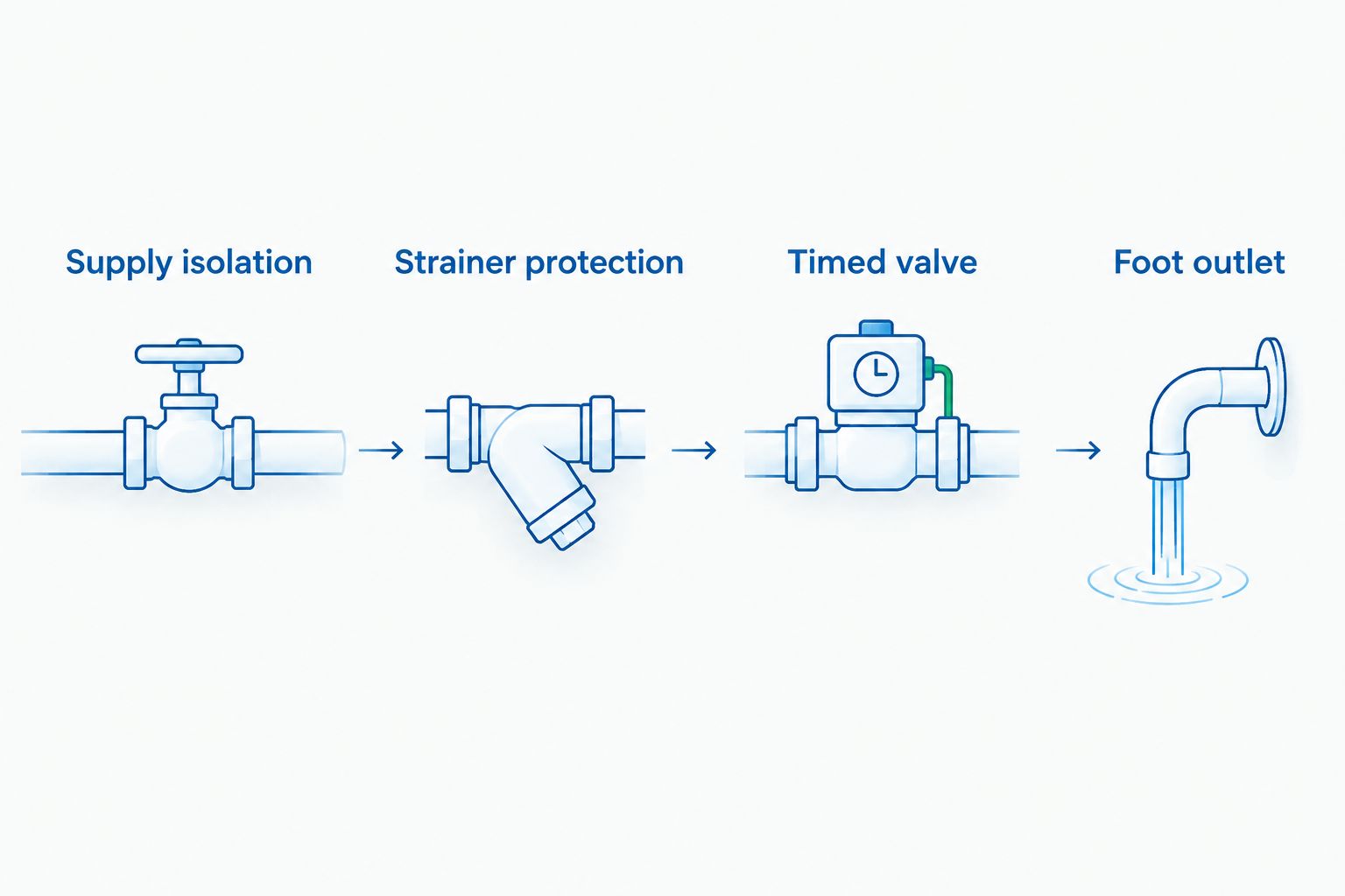
The diagram shows the control concept, not a permit-ready plumbing drawing. Your installer must add the backflow assembly, drainage provisions, and other components required for the actual site.
Water connection and leak checks
- Close the branch shutoff, isolate electrical power, and relieve water pressure through an appropriate outlet. Confirm that the branch is depressurized before opening a joint.
- Flush the supply piping before connecting the solenoid. Keep construction debris and thread-sealing material out of the valve's internal passages.
- Install the specified strainer and valve in their permitted orientations. Follow the valve body's flow-direction marking; do not assume that either port can serve as the inlet.
- Make the fixture connection using the specified thread or fitting system. Apply only the sealing method and tightening procedure approved for those materials, and use wrench flats rather than the coil as a handle.
- Reopen the supply slowly with the solenoid de-energized. Inspect all joints for leakage, then perform the manufacturer's prescribed pressure and functional checks.
Expected result: The piping remains dry externally, and the normally closed valve does not pass sustained flow while de-energized. Brief discharge from water already downstream is different from continuous leakage through the valve.
Do not use the controller to conceal a plumbing fault. If the outlet runs continuously with power isolated, correct the valve orientation, debris problem, manual override position, or internal sealing fault before wiring proceeds.
Include this inspection in the 2026 commissioning record. Record the installed valve model, flow direction, measured supply conditions, and any manufacturer-required adjustments rather than copying values from another installation.
Controller wiring and cycle setup
Match the electrical connections
- Have the electrician compare the controller output with the solenoid coil nameplate. Voltage alone is insufficient: AC or DC type, load rating, starting demand, and duty rating must also match.
- Identify whether the controller supplies power or provides a dry relay contact. A dry contact switches a separately supplied circuit; it does not generate coil power by itself.
- Connect the approved momentary trigger to the designated controller input using the manufacturer's wiring diagram. Do not connect a hydraulic button or an unverified sensor output to an electrical input.
- Terminate the valve circuit, protective connections, and power supply as specified. Use suitable outdoor enclosures, cable entries, and electrical protection, including GFCI protection where required.
- Close and secure all enclosures before restoring power. Never test exposed energized terminals beside a wet fixture.
Expected result: The controller powers up correctly, the trigger registers, and the valve remains closed until the intended command occurs.
Terminal names and menu labels vary by controller. Use the exact markings on the selected equipment; a generic terminal-to-terminal wiring recipe is not a substitute for its diagram.
Configure the timed rinse
- Select the documented function that energizes the output immediately after a trigger and releases it after the set interval. Do not confuse it with an on-delay function, which waits before energizing.
- Set the approved rinse duration. If the project calls for a 15-second cycle, enter 15 seconds using the controller's documented time range and units; this is a project setting, not a universal foot-wash requirement.
- Configure repeat-trigger behavior. Specify whether another press restarts the interval, is ignored during a cycle, or starts another cycle afterward, using only functions the controller supports.
- Test 1 complete cycle from a momentary press, including automatic shutoff. Then test 3 consecutive cycles as a commissioning check, recording the observed operation rather than assuming the display proves it.
- Test power interruption and restoration under controlled conditions. Confirm the valve closes when de-energized and that power restoration does not start an unintended rinse.
Expected result: A deliberate trigger produces the approved rinse, timeout closes the valve, and repeated presses behave as specified.
Keep the final timer setting and restart behavior in the 2026 handover sheet. A correctly programmed timer is not proof of a correctly closing water valve. Observe the outlet during every functional test.
Second workflow: disable rinsing outside opening hours
A scheduled enable function is useful when a facility needs user-triggered rinses during opening hours but no operation after closing. Keep the individual rinse timer responsible for each cycle; use the schedule only to permit or inhibit operation.
- Confirm that the controller provides a documented enable input or compatible scheduling function. Do not improvise by switching arbitrary control wires.
- Program the permitted operating window and verify the controller's clock, day selection, and behavior after a power interruption.
- Test a trigger inside the permitted window, then outside it. Check what happens when closing time occurs during an active rinse.
- Document an authorized maintenance procedure without leaving a permanent override enabled.
Expected result: Users receive timed rinses during permitted hours, and the station does not start a new rinse outside the programmed window.
For a 2026 seasonal facility, assign responsibility for schedule changes and clock checks. Scheduled closure is not physical isolation for maintenance and does not drain the valve for freezing weather.
Troubleshooting
The controller activates, but no water flows
Check the branch shutoff, strainer, valve direction, and downstream fixture control first. A solenoid cannot force water through a closed manual valve.
Have the electrician verify the correct coil supply during the commanded cycle. If the valve is pilot-operated, compare actual differential pressure with its documented operating requirements; clicking alone does not establish that it opened.
Water continues after the timer finishes
Isolate the branch if flow will not stop. Have the electrician determine whether the coil remains energized after timeout, then separate a controller fault from a mechanical valve fault.
With power safely isolated, inspect the documented manual override position and arrange valve service for debris or damaged internal seals. Do not repeatedly cycle a leaking valve as a substitute for repair.
The valve chatters or produces weak flow
Check the electrical supply under load, coil compatibility, clogged strainer, and pressure conditions. Undervoltage and incorrect operating conditions can prevent stable operation.
Compare valve sizing and pressure loss with the required fixture flow. Do not drill a restrictor or change the outlet to compensate for an incorrectly selected valve.
Shutoff produces a pipe bang
Fast closure can create water hammer. Have the plumber assess pipe support, supply pressure, valve closure characteristics, and whether a correctly selected arrestor is required.
Increasing the timer duration does not correct the pressure transient at closure. Resolve the hydraulic cause before accepting the installation.
The station stops working after freezing weather
Isolate water and power before inspecting for damage. A closed solenoid can still contain trapped water, and an outdoor enclosure rating does not establish freeze resistance.
Inspect the complete branch before returning it to service. Replace damaged components and correct the winterization procedure rather than simply resetting the controller.
Customize your workflow
Before ordering from The Fountain Direct, give the installer the fixture selection and require a matching control submittal. That submittal should identify the valve, controller, trigger, power supply, service access, and approved connection method.
For The Fountain Direct foot wash stations, separate fixture selection from control approval: the product's material or connection style does not prove timer compatibility. Approve the complete assembly before purchasing retrofit parts.
Expand the installation plan to include runoff management, cleaning access, and seasonal shutdown. Assign a maintenance owner and keep the fixture and controller documents together so a replacement part is selected by specification, not appearance.
FAQ
How do I connect a foot wash station to a timed solenoid valve?
Install a compatible normally closed solenoid in the dedicated supply branch and connect it through its matched controller and approved trigger. Confirm fixture approval, plumbing protection, electrical compatibility, and automatic shutoff before use.
Can I use the existing foot-wash push button to trigger a solenoid?
Only use the existing button if its manufacturer documents a compatible electrical output or an approved interface. A hydraulic push button is not an electrical switch and must not be wired as one.
Does a timed foot wash station need another timer?
No additional timer is needed when the existing timed operation meets the project requirement. Adding electronic controls requires a separate compatibility review and an approved operating arrangement.
Should the solenoid valve be normally closed?
A normally closed solenoid is the appropriate starting point for a rinse that must stop when coil power is removed. Confirm the selected valve's operating requirements and test the complete assembly during commissioning.
What voltage should a foot-wash solenoid use?
Use the voltage and AC or DC supply specified on the selected valve's coil nameplate. The controller, power supply, electrical protection, and outdoor installation must match that specification.
Can a timer control a hot-and-cold foot wash station?
A timer can control an approved tempered-water arrangement when the fixture, mixing controls, and solenoid are designed for that configuration. A timer does not regulate temperature or replace required scald protection.
Will a timed solenoid prevent the station from freezing?
No, a timed solenoid does not provide freeze protection. Water can remain trapped inside the valve and downstream piping after shutoff, so follow a winterization procedure covering the entire assembly.
One last thing
Test the closed condition as carefully as the rinse. A station that sprays correctly but leaks after timeout has failed commissioning, even when the controller reports that its cycle has ended.
Photograph the installed nameplates and retain the approved wiring diagram inside the maintenance file. Those details make a future coil or controller replacement a specification check instead of a guess.